(artname: pmgrab80.EPS)

This chapter describes the switch terminal interface. The terminal interface panels are automatically refreshed every few seconds to provide you with current information.
| Note: | The panels shown in this chapter are intended to be representative and should not be assumed to be entirely accurate because they are subject to change before final shipment of the product. |
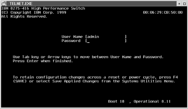
The Login panel is the first panel displayed when initializing the terminal interface. Figure 13 shows the Login panel; you need an approved user name and password to login.
Figure 13. Login panel for terminal interface
 (artname: pmgrab80.EPS) |
The terminal interface provides a way to log out. From the Main Menu, select LOGOUT or select System Utilities Menu, then select Logout. When you have finished using the terminal interface, ensure you have saved all configuration changes before logging out.
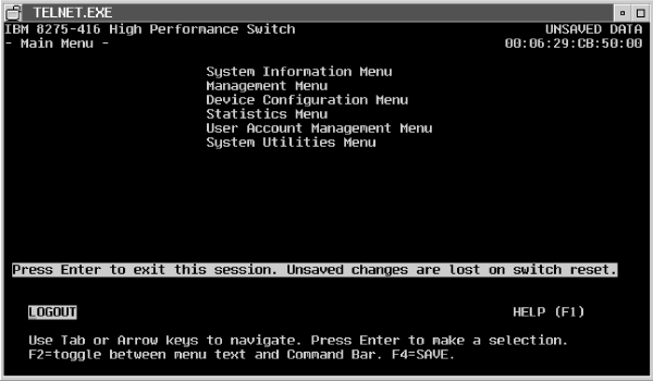
Following a successful login, the Main Menu appears (Figure 14). Information following in this section is arranged in the order of topics on the Main Menu.
Figure 14. Main menu for terminal interface
 (artname: pmgrab99.EPS) |
The switch manages information about its installed hardware and software. System information contains read-only and read/write fields. The read-only fields are written when the switch is manufactured. Through configuration you can change only the read/write fields: System Name, System Location and System Contact. Changes to these fields must be saved to be effective. A reset is not necessary for the changes to be effective.
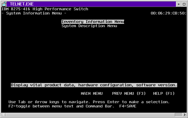
To access system information, select System Information Menu on the Main Menu. By selecting Inventory Information Menu and System Description Menu, you can view information about your switch. Figure 15 shows your system information options.
Figure 15. System information menu
 (artname: pmgrab00.EPS) |
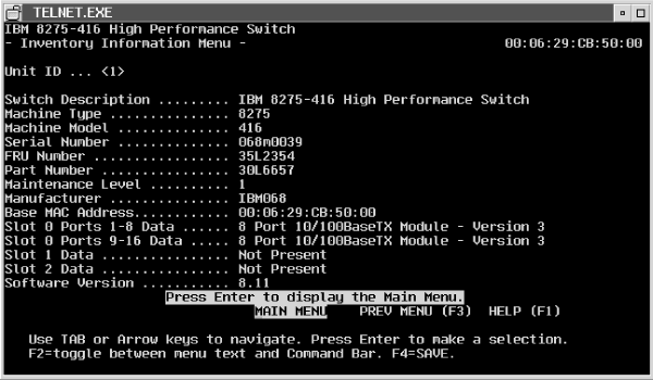
Figure 16 shows the Read-Only inventory information available for your switch.
Figure 16. Inventory information menu
 (artname: pmgrab02.EPS) |
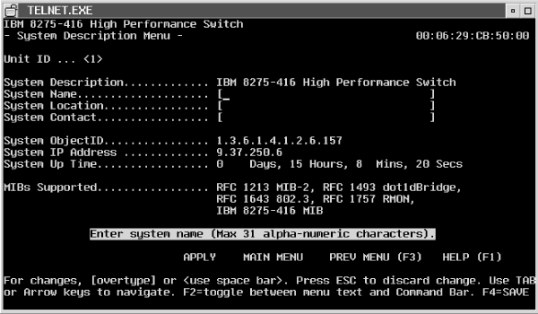
Figure 17 shows the system information for your switch.
Figure 17. System description menu
 (artname: pmgrab04.EPS) |
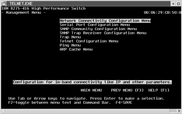
Select Management Menu on the Main Menu (Figure 18) to use the management functions of the switch.
 (artname: pmgrab87.EPS) |
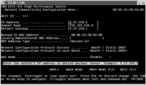
To configure the IP information, select Management Menu from the Main Menu, then select Network Connectivity Configuration Menu from the Management Menu. The Network Connectivity Configuration Menu appears as shown in Figure 19.
Figure 19. Network connection configuration
 (artname: pmgrab07.EPS) |
You must configure the following IP information to establish in-band connectivity to the switch:
| Note: | Disabling the Web interface will not disable Web sessions that are in progress; no new Web sessions will be started. |
The switch allows you to access the switch through the serial EIA 232 port. This type of connectivity is called out-of-band connection. See Accessing the switch for descriptions of ways to access the switch.
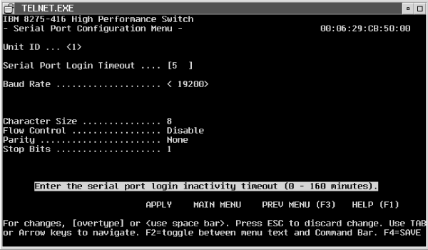
On the Main Menu, select Management Menu. From the Management Menu, select Serial Port Configuration Menu. Figure 20 shows the parameters to configure the serial EIA 232 port.
Figure 20. Serial port configuration
 (artname: pmgrab09.EPS) |
You specify Login Timeout and Baud Rate:
If you do not want to manually configure the switch with IP information, the switch can obtain the IP information from a BootP or DHCP server. The switch must be accessible through a port which is a member of the Default VLAN ID 1. When BootP or DHCP is enabled, the switch periodically sends out requests until a response is received from either a DHCP or BootP server. The IP information in the BootP or DHCP response overlays any existing IP information in switch. The new IP information is not retained across a reset until you select Save.
| Note: | If you configure a switch with an IP address, then DHCP frames will effectively be ignored (that is, the configured IP address will have priority over the address received via DHCP). However, BootP frames will have priority over a configured IP address. A difference between BootP and DHCP frames is that DHCP frames have 0xFFFFFFFFFFFF as the destination MAC address, while BootP frames have the switch's individual MAC address as the destination address. |
To configure the DHCP server for static DHCP, you must specify an IP address that will be assigned to the switch. This IP address is mapped to the switch's MAC address. The static DHCP does not obtain an IP address from a pool of addresses on a DHCP server unless one is explicitly set up for a given MAC address. For example, In Windows NT(R), you must set up a reservation for the switch's MAC address. Assign an IP address from the pool of current addresses. Configure the router, IP address, and subnet mask for the switch's MAC address. The switch supports no other DHCP options.
For BootP, the BootP server must have the appropriate information configured for the switch. A newly installed switch broadcast a BootP request over IP when it is powered on or reset. The BootP server, using information from its BOOTPTAB file, provides the switch with configuration information.
The following is an example of a BOOTPTAB file entry containing configuration information for the switch:
8275_416_Switch_1:ht=ethernet:ha=0004ac6b0980:\
         ip=10.1.7.7:gw=10.1.1.1:\
         sm=255.255.255.0

8275_416_Switch_2:ht=ethernet:ha=0004ac6b09C0:\
         ip=10.1.7.8:gw=10.1.1.1:\
         sm=255.255.255.0
Where:
| ht | hardware type |
| ha | host hardware address |
| ip | host IP address |
| gw | gateway address list |
| sm | subnet mask |
Configuration information obtained from the BootP server is not saved unless you select SAVE. Next, configure the Network Configuration Protocol.
If you are using DHCP or BootP, you must configure the appropriate information for the switch. To do so, configure the Network Configuration Protocol as follows:
The switch has an SNMP agent that complies with SNMP Version 1 (SNMPv1). For more about the SNMP specification, see the appropriate SNMP RFCs. The SNMP agent sends traps through TCP/IP to an external SNMP manager based on your SNMP configuration. SNMP configuration for the switch includes configuring the trap receiver and SNMP community parameters, which are described in the following text.
If you do not use the default community information, you must configure the SNMP agent with a community name for the switch. A community name is a name associated with the switch and with a set of SNMP managers allowed to manage it with a specified privileged level. You can add, change or delete communities. The switch does not have to be reset for changes to take effect. Up to six communities are simultaneously supported.
Community names in the SNMP community table must be unique. If you make multiple entries using the same community name, the first entry is kept and processed and all duplicate entries are ignored.
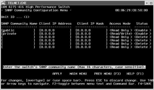
To configure your SNMP communities, select SNMP Community Configuration Menu from the Management Menu. Figure 21 shows SNMP community information you need to specify.
Figure 21. SNMP community configuration
 (artname: pmgrab11.EPS) |
| Note: | If the Client IP Mask is set to 0.0.0.0, a Client IP Address of 0.0.0.0 matches all IP addresses. |
To have a specific IP address be the only authenticated IP address, set the Client IP Address to the required IP address and set the Client IP Mask to 255.255.255.255. The default for the Client IP Mask is 0.0.0.0.
A community name with read-only access is restricted from viewing SNMP community and SNMP trap receiver information.
A community status of Enable/Active means that the community is active, allowing SNMP managers associated with this community to manage the switch according to its access right.
A community status of Disable/Inactive means that the community is not active; no SNMP requests using this community will be accepted. In this case the SNMP manager associated with this community cannot manage the switch until the Status is changed back to Enable/Active.
A community status of Delete means that this name will be removed from the table. The default Status values for the default private and public community names are both Enable/Active. The default value is Delete/Inactive for the 4 undefined community names.
Trap messages are sent across a network to an SNMP Network Manager. These messages alert the manager to events occurring within the switch or on the network. Up to six simultaneous trap receivers are supported.
IP Addresses in the SNMP trap receiver table must be unique. If you make multiple entries using the same IP address, the first entry is kept and processed and all duplicate entries are ignored.
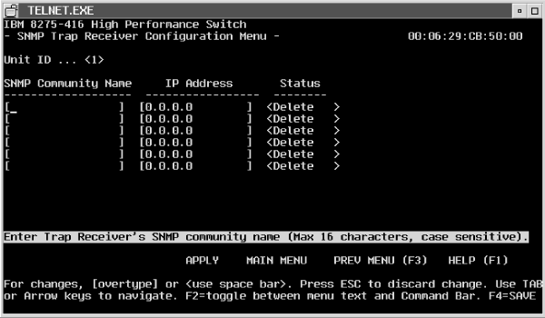
To configure trap receivers, select SNMP Trap Receiver Configuration Menu on the Management Menu. Figure 22 shows the parameters you need to specify.
Figure 22. SNMP trap receiver configuration
 (artname: pmgrab13.EPS) |
Trap receiver parameters are:
You can optionally configure which traps that the switch should generate. You do this by selecting a status for the trap condition, that is, if it is either enabled or disabled. If a trap condition is enabled and the condition is detected, the switch's SNMP agent sends the trap to all enabled trap receivers. Otherwise, no condition is detected and no trap is sent. The default Status value for all Trap Conditions is Enabled. The switch does not have to be reset to implement the changes. Cold start traps are always generated; there are no associated trap conditions.
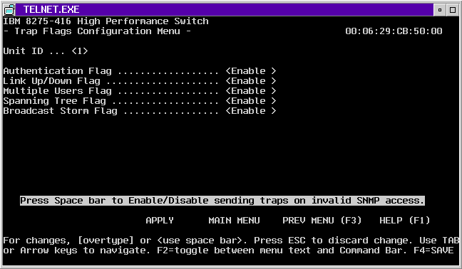
To configure trap conditions, select Trap Menu from the Management Menu. From the Trap Menu, select Trap Flag Configuration Menu, then enable or disable trap flags.
Figure 23 shows the trap flags that you can set.
Figure 23. Trap flags configuration
 (artname: pmgrab21.EPS) |
These are the trap conditions that can be enabled/disabled:
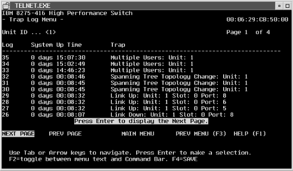
The switch maintains a Trap Log; it contains a maximum of 256 entries that wrap. Trap Log information is not retained across a switch reset.
Select Trap Menu from the Management Menu, then select Trap Log Menu from the Trap Menu. Figure 24 shows the entries in the trap log.
 (artname: pmgrab16.EPS) |
Each entry contains:
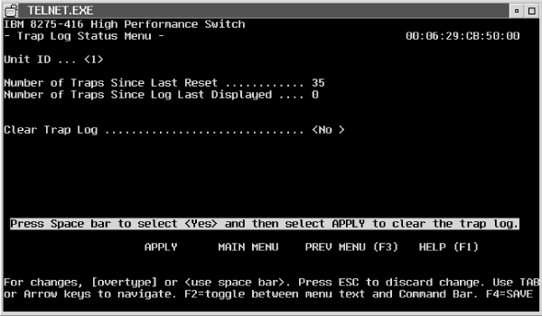
To check how many traps have been generated, select Trap Menu from the Management Menu, then select Trap Log Status Menu from the Trap Menu.
You can choose to clear the trap log on this panel (Figure 25).
 (artname: pmgrab23.EPS) |
You can perform this operation on this panel:
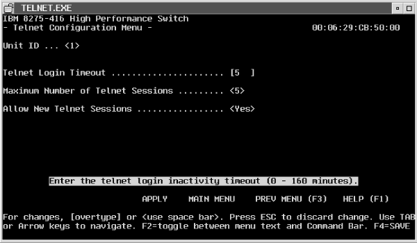
You can manage the switch remotely using a Telnet connection. Accessing the switch describes setting up a Telnet connection. To configure for Telnet, select Management Menu from the Main Menu, then from the Management Menu, select Telnet Configuration Menu (Figure 26).
Figure 26. Telnet configuration
 (artname: pmgrab25.EPS) |
The following parameters are for configuring a Telnet session with the switch:
| Note: | Changing the timeout value for active sessions does not become effective until the session is reaccessed. Any keystroke will also activate the new timeout duration. |
The switch provides a ping utility that you can use to check connectivity between devices in a network. To use ping, the switch must be configured correctly for network (in-band) connection. The source and target devices must have the ping utility enabled and running on top of TCP/IP. The switch can be pinged from any IP workstation with which the switch is connected through the Default VLAN (VLAN 1) (as long as there is a physical path between the switch and the workstation). The terminal interface allows you to send one ping, three pings or a continuous ping (one every second) to the target station.
To use Ping, select Management Menu from the Main Menu. Then select Ping Menu from the Management Menu (Figure 27).
 (artname: pmgrab27.EPS) |
You must supply this information:
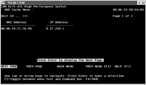
Select Management Menu from the Main Menu. Then select ARP Cache Menu from the Management Menu to displays the ARP cache for the switch.
This is used to check connectivity between the switch and other devices. The ARP cache identifies the MAC addresses of the IP stations communicating with the switch. Figure 28 shows ARP Cache information.
 (artname: pmgrab29.EPS) |
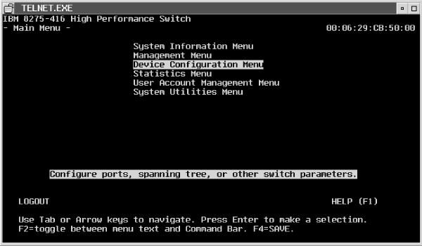
To configure the switch, select Device Configuration Menu on the Main Menu. Figure 29 shows your options.
Figure 29. Device configuration
 (artname: pmgrab30.EPS) |
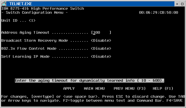
The switch allows you to set a time after which the address will timeout, and to enable/disable broadcast storm recovery and 802.3x flow control. To set these values, select Device Configuration Menu from the Main Menu and then select Switch Configuration Menu (Figure 30).
Figure 30. Switch configuration
 (artname: pmgrab32.EPS) |
The value you specify is:
When you specify Enable for Broadcast Storm Recovery and the broadcast traffic on any Ethernet port exceeds 20 percent of the link speed, the switch blocks (discards) the broadcast traffic until the broadcast traffic returns to 10 percent or less.
When you specify Disable for Broadcast Recovery Mode, then the switch will not block any broadcast traffic on any Ethernet port. The default is Disable.
The switch is shipped from the factory with default port settings that allow it to automatically determine the port type and speed.
See Configuring your switch for details about making and saving configuration changes.
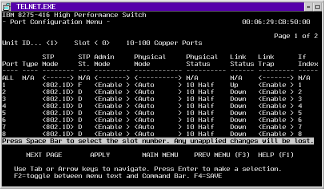
To configure the ports, select Device Configuration Menu from the Main Menu, then select Port Configuration Menu from the Device Configuration Menu (Figure 31).
 (artname: pmgrab34.EPS) |
You can select or change the following values:
Note that when All is specified and you specify Disable in the Admin Mode field, you lose in-band connection to the switch.
Indicates the port number.
The feature slots are Slot 1 and Slot 2. Available feature modules have 2, 4, and 8 ports.
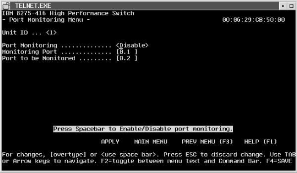
You can select any of the Ethernet ports as a probe to monitor forwarded traffic (not local traffic) with an external network analyzer. The selected probe port can monitor (mirror) traffic from one port. The selected probe port also receives and transmits network traffic (tagged frames) which allows a device connected to the probe port to be managed over the network (in-band connectivity). However, the device must be 802.1Q aware to be remotely managed by the switch.
The monitoring port forwards frames with a VLAN membership which matches the monitored port. The monitoring port transmits all frames as tagged. The monitoring port does not participate in Spanning Tree Protocol (STP) and is always in a forwarding state when the link is up. The monitoring port does not forward local traffic, and it does not participate in GVRP.
From the Main Menu, select Device Configuration Menu and then, select Port Monitoring Menu from the Device Configuration Menu (Figure 32).
 (artname: pmgrab37.EPS) |
Specify values for the following parameters:
When Port Monitoring is Enabled, make sure that the monitoring port is connected to a network analyzer and not to the network itself to avoid potential problems.
The switch participates in Spanning Tree Protocol (STP). STP allows you to configure redundant paths in the switch topology. The switch automatically blocks redundant paths to prevent loops (that is, make it fault tolerant). If an active path is broken and a backup path is available, the switch finds the redundant path and enables it. Without STP, a path failure means loss of connectivity for the affected part of the network.
The switch complies with the IEEE 802.1D standard. Refer to the IEEE 802.1D document for STP specifications. The switch supports one Spanning Tree Protocol (STP) for the entire switch.
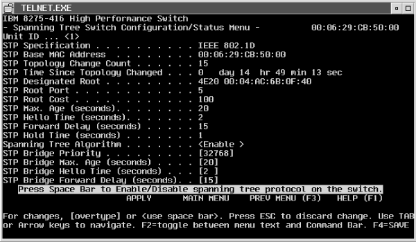
To configure the Spanning Tree Protocol for the switch, select Device Configuration Menu from the Main Menu, then select Spanning Tree Switch Configuration/Status Menu or Spanning Tree Port Configuration/Status Menu from the Device Configuration Menu (Figure 33).
Figure 33. Spanning tree switch configuration/status
 (artname: pmgrab39.EPS) |
The following section lists and describes the STP configuration functions and related parameters.
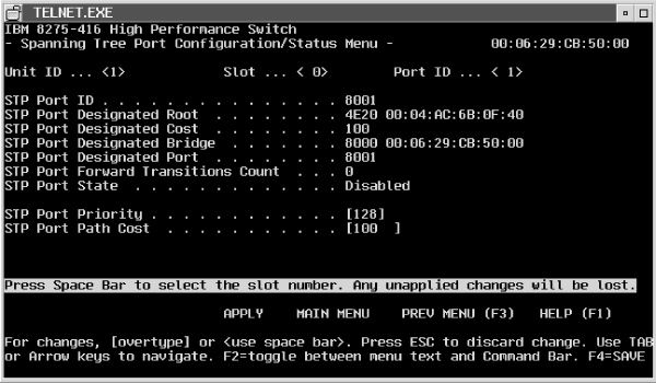
You can configure the Spanning Tree Protocol by ports. Select Device Configuration Menu from the Main Menu. Then select Spanning Tree Port Configuration/Status Menu from the Device Configuration Menu (Figure 34).
Figure 34. Spanning tree port configuration/status
 (artname: pmgrab41.EPS) |
The parameter values are:
Appendix E, Introduction to Virtual LANs (VLANs) provides an introduction to the terminology and concepts for VLANs. It is helpful to review this material before you define values for the parameters associated with configuring VLANs.
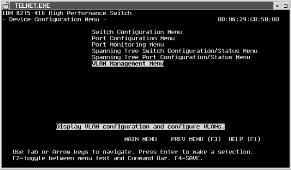
From the Main Menu, select Device Configuration, and then select VLAN Management Menu to begin configuring VLANs for your switch (Figure 35).
Figure 35. VLAN management menu
 (artname: pmgrab42.EPS) |
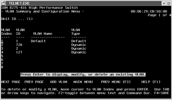
From the VLAN Management Menu, select VLAN Summary and Configuration Menu to begin configuring your VLANs (Figure 36). Note that there are four panels on which you can define a total of 32 VLANs.
Figure 36. VLAN summary and configuration
 (artname: pmgrab44.EPS) |
The parameters for this panel are:
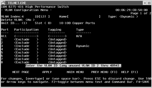
If you want to add a VLAN, move the cursor to the ADD VLAN command at the bottom of the panel and press Enter. To modify an existing VLAN, move the cursor to the line containing the VLAN and press Enter. You will be presented the VLAN Configuration Menu (Figure 37).
Figure 37. VLAN Configuration Menu
 (artname: pmgrab95.EPS) |
The parameters for this panel are:
If a monitoring port is configured, its VLAN membership always follows the VLAN membership of the port being monitored. However, the VLAN Configuration Menu always displays the monitoring port's actual configuration; this configuration will take effect when the port is no longer a monitoring port.
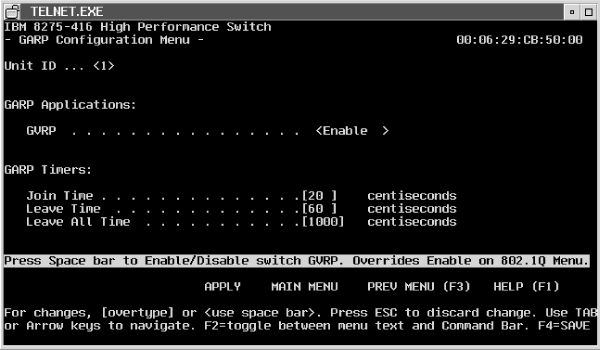
See Figure 38 for the GARP configuration parameters.
 (artname: pmgrab49.EPS) |
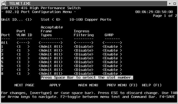
See Figure 39 for parameters used to configure your 802.1Q ports.
Figure 39. 802.1Q port configuration
 (artname: pmgrab51.EPS) |
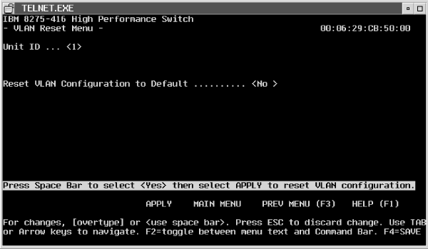
This function allows you to reset VLAN configuration parameters to those default parameters provided by the factory.
See Figure 40 for an example of the panel used to reset a VLAN.
 (artname: pmgrab54.EPS) |
Link aggregation, also called trunking, allows multiple 802.3 MAC interfaces to be grouped together logically to appear as one super-link. The super-link or Link Aggregation Group (LAG) has access to the combined bandwidth of all links. Link aggregation also provides automatic, point-to-point redundancy between two devices (switch-to-switch). Each link in the trunk must be running at the same link speed and in full-duplex mode (half-duplex mode is not supported).
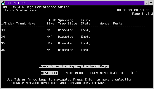
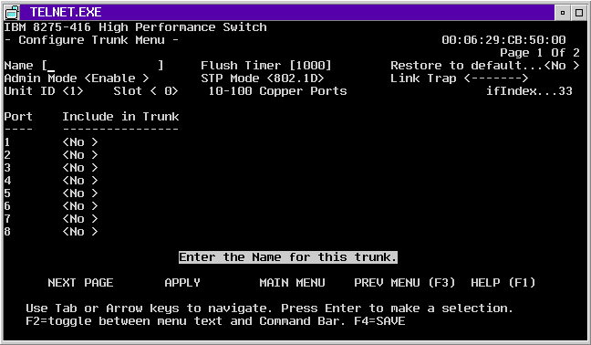
To configure (or create) a trunk, select Device Configuration on the Main Menu, then select Trunk Management. The Trunk Status Menu (Figure 41) is displayed; it consist of two panels; Page 1 of 2 and Page 2 of 2. You can define up to four trunks on each of these panels for a total of 8 trunks. To Configure a trunk, complete the configuration information on the Trunk Status Menu, then move the cursor to the ifIndex field, press Enter, and the Configure Trunk Menu (Figure 42) is displayed. Complete the configuration information on the Configure Trunk Menu.
 (artname: pmgrab60.EPS) |
Figure 42. Configure trunk menu
 (artname: pmgrab61.EPS) |
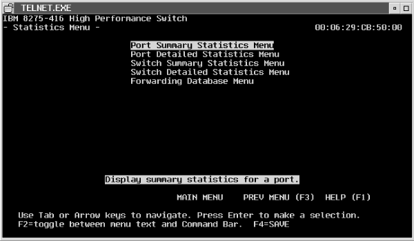
To access statistics, select Statistics Menu on the Main Menu. Traffic statistics are kept by port. Details and summaries of packets broadcast, transmitted, and switched, as well as error packets and discarded packets are the types of statistics kept for your switch.
Figure 43 shows the types of statistics that you can select to view from the Statistics Menu.
After making your selection, the panels containing statistics will refresh every few seconds. All counters may not update every few seconds. Even though the refresh rate is every few seconds, some counters will not change. For example, the Self-Learning Statistics counters update on an as needed basis whenever a host gets updated.
| Note: | A description for each statistic may be obtained by pressing Help on the associated Web statistics panel. |
 (artname: pmgrab56.EPS) |
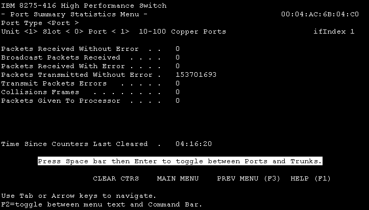
To view a summary of port statistics, select Port Summary Statistics Menu from the Statistics Menu. See Figure 44 for a summary of port statistics that are collected.
Figure 44. Port summary statistics
 (artname: fgl2a003.EPS) |
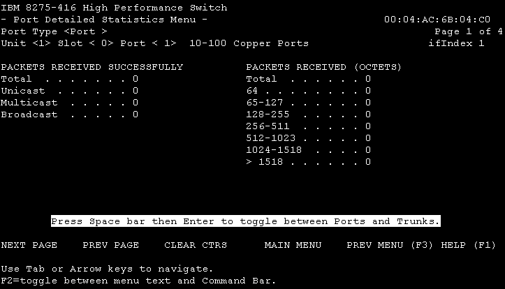
To view detailed port statistics, select Port Detailed Statistics Menu from the Statistics Menu (Figure 45). Detailed port statistics are collected and can be viewed on four consecutive panels. To view the next panel, move the cursor to NEXT PAGE (at the bottom of each panel) and press Enter.
Figure 45. Port detailed statistics
 (artname: fgl2a004.EPS) |
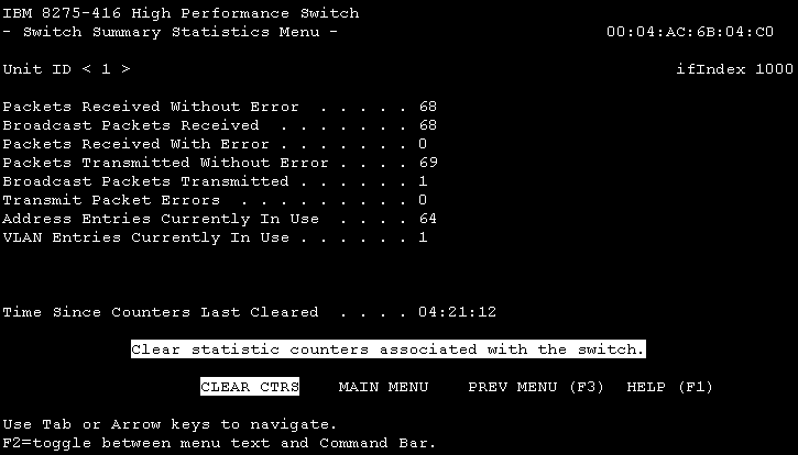
To view a summary of switch statistics, select Switch Summary Statistics Menu from the Statistics Menu. See Figure 46 for a summary of the switch statistics that are collected.
Figure 46. Switch summary statistics
 (artname: fgl2a005.EPS) |
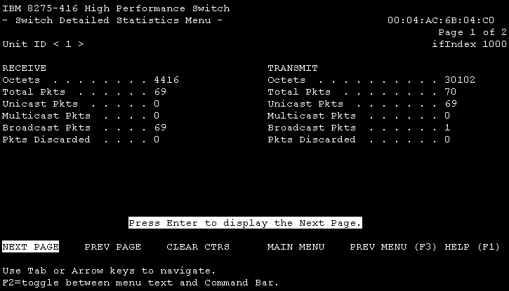
To view detailed switch statistics, select Switch Detailed Statistics Menu (Page 1 of 2) from the Statistics Menu. See Figure 47 for the detailed switch statistics that are collected.
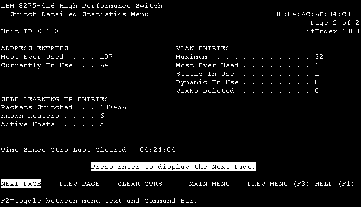
To view Self Learning IP statistics, select Switch Detailed Statistics Menu (Page 2 of 2) from the Statistics Menu. See Figure 48 for an example of the statistics that are collected for Self Learning IP.
Figure 47. Switch detailed statistics
 (artname: fgl2a006.EPS) |
Figure 48. Self Learning IP statistics
 (artname: fgl2a007.EPS) |
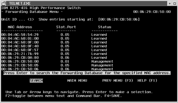
To view forwarding database information, select Forwarding Database Menu from the Statistics Menu. See Figure 49 for the forwarding database information.
Figure 49. Forwarding database information
 (artname: pmgrab69.EPS) |
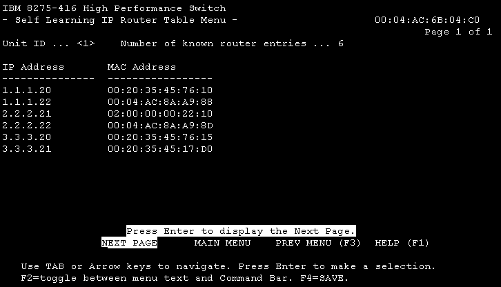
To view statistics about known routers whenever the Self Learning IP function is enabled, select Statistics Menu from the Main Menu, then select Self Learning IP Router Table Menu. See Figure 50 for the router statistics.
Figure 50. Self Learning IP router table menu
 (artname: fgl2a008.EPS) |
The description of the information collected is:
Notes:
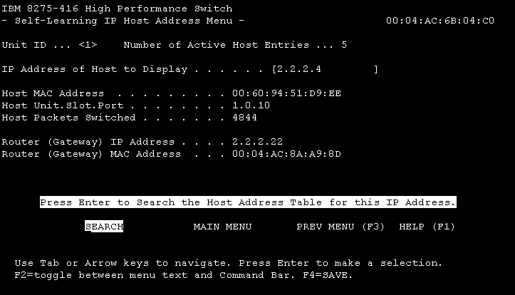
To view information about IP host addresses that are collected when the Self Learning IP function is enabled, select Statistics Menu from the Main Menu, then select Self Learning IP Host Address Menu. See Figure 51 for the host IP statistics.
Figure 51. Self Learning IP host address menu
 (artname: fgl2a009.EPS) |
Notes:
On the Main Menu, select User Account Management Menu to use the functions for managing user accounts.
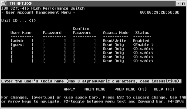
On the User Account Management Menu, select User Accounts Menu. Figure 52 shows the User Accounts Menu where you specify user names, passwords, and access mode.
Figure 52. User account management
 (artname: pmgrab71.EPS) |
The switch allows you to add and delete users and set user passwords for the switch. You are to provide the following information:
A user with read only access is restricted from accessing the SNMP Community Configuration menu, SNMP Trap Receiver Configuration menu, User Account Management menu, and System Utilities menu. When a read only user tries to modify a configuration parameter on a menu, the data is not accepted and is not processed.
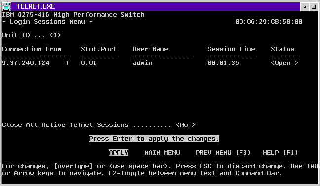
On the User Account Management Menus, select Login Sessions Menu (Figure 53), which allows you to close a single session or close all active Telnet sessions.
Figure 53. Login session management
 (artname: pmgrab72.EPS) |
These fields are read-only:
These fields are configurable
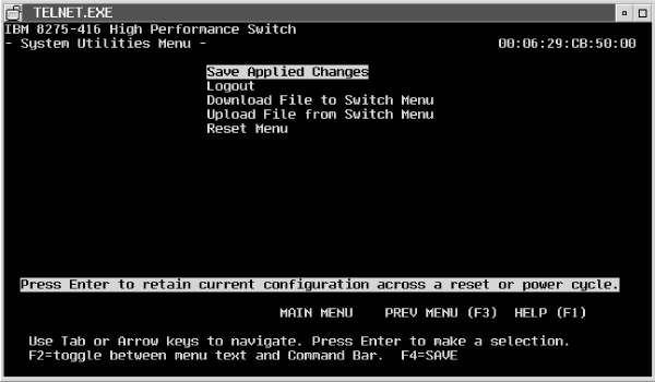
The system utilities can be used only by users with read/write access. You can use the system utilities by selecting System Utilities Menu on the Main Menu. Figure 54 shows the available utilities.
To permanently save configuration changes either select F4 to save or go to the System Utilities Menu and select Save Applied Changes, as shown in Figure 54.
Figure 54. Save applied changes
 (artname: pmgrab73.EPS) |
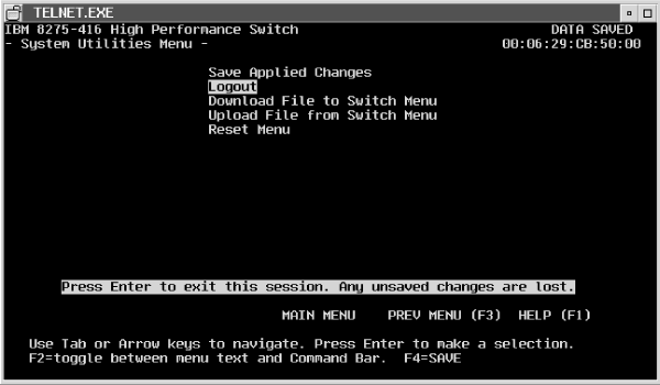
When you have finished using the terminal interface, ensure you have saved and applied all configuration changes before you log out. The terminal interface provides an orderly way to log out. One way is to use the LOGOUT command on the Main Menu. Another way to log out is to select System Utilities Menu from the Main menu, then select Logout as shown in Figure 55.
 (artname: pmgrab74.EPS) |
To upload or download a file, select System Utilities Menu from the Main Menu. Then make the appropriate selection from the System Utilities Menu.
The switch can download or upload files. Downloading is the transfer of files from a remote server into the switch. Uploading is the transfer of files from the switch to a remote server.
You can retrieve configuration settings from the switch as a binary file and send a binary configuration file to the switch. This allows you to back up the configuration or to easily update the configuration of multiple switches. Additionally, you can provide a configuration file to IBM support personnel for problem determination.
The last-saved configuration used by the switch is retained after a code update or a reset.
The switch displays result messages to indicate the status of a file transfer. Table 11 and Table 12 show the messages along with explanations for each.
Table 11. Messages - while downloading files
| Message | Explanation |
|---|---|
| TFTP in progress... | The switch has initiated the file transfer with the TFTP server. |
| Can't start...previous transfer is not complete yet! | Another TFTP operation is still taking place. Only one TFTP operation can occur at a given time. This includes both download and upload operations. Wait until the previous operation completes. |
| TFTP receive complete...storing in flash... | For Code only: The file has been successfully transferred to the switch and passed all the verification tests. It is now being stored permanently in flash memory. |
| TFTP receive complete... updating configuration | For Configuration only: The switch has received the file and will verify its integrity. The file will be stored in flash if it passes the integrity checks. The switch will reset itself after storing the file in order for the newly loaded configuration to take effect. |
| File transfer operation completed successfully. | The file has successfully been stored in flash. The switch must be reset now for the new code to become operational. |
| File failed CRC check! | The switch received the file, but detected a CRC error. Because the file is corrupted, it will not be stored in flash. Try obtaining another copy of the file. |
| This file is not intended for this product! | The switch received the file, but detected that the file was not meant for the switch. The file will not be stored in flash. If this is for a code update, obtain the correct software image from the IBM Web site. If this is for configuration, make sure that the configuration file originated from a 8275-416 switch. |
| Failure while storing in flash! | The switch successfully received the file, and began storing the image in flash; however, an error occurred during the process. For code only, the flash is most likely corrupt now and new code will have to be downloaded via the bootcode utility function. For configuration, retry the download. If the file transfer still fails, contact your IBM service representative. |
| File transfer failed! | A general error occurred. The most likely cause for this message is when the switch cannot complete the TFTP operation. This may happen if you have not entered the correct IP address for the TFTP server, or if an IP address has not been set up on the switch. Check to see if your IP addresses are configured correctly. Also, make sure that you can ping the TFTP server from the Ping Menu. This error could also occur if you entered an incorrect path or file name. Check to make sure these fields match the file location on the TFTP server. |
Table 12. Messages - while uploading files
| Message | Explanation |
|---|---|
| TFTP in process... | The switch has initiated the file transfer with the TFTP server. |
| Can't start...previous transfer is not complete yet! | Another TFTP operation is still taking place. Only one TFTP operation can occur at a given time. This includes both download and upload operations. Wait until the previous operation completes. |
| Error while preparing file for transfer. | Before uploading a file, the switch must prepare that file for transfer. This message means that there was a problem either in reading the information required for making the file, or there was a problem creating the file. Contact your IBM service representative. |
| File transfer failed! | A general error occurred. The most likely cause of this message is when the switch cannot complete the TFTP operation. This may happen if you have not entered the correct IP address for the TFTP server, or if an IP address has not been set up on the switch. Check to see if your IP addresses are configured correctly. Also, make sure that you can ping the TFTP server from the Ping Menu. This error could also occur if you entered an incorrect path or file name. Check to make sure these fields match the file location on the TFTP server. |
| File transfer completed successfully | The switch successfully sent the file to the TFTP server. |
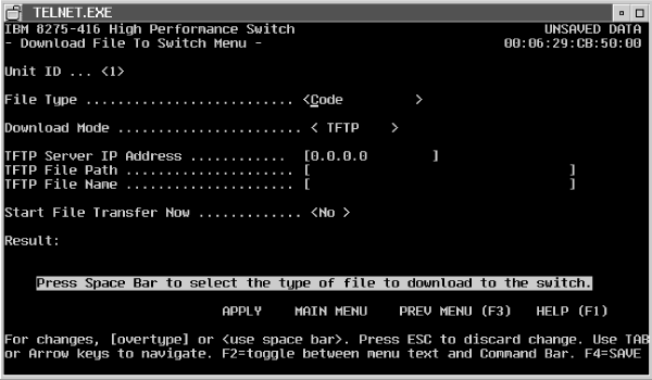
Downloading is the transfer of files from a remote server into the switch. The download operation is initiated by selecting Download File to Switch Menu on the System Utilities Menu (Figure 56). While the download is in process, you may see messages displayed. Table 11 shows messages that can appear during the download process.
Figure 56. Downloading a file to the switch
 (artname: pmgrab75.EPS) |
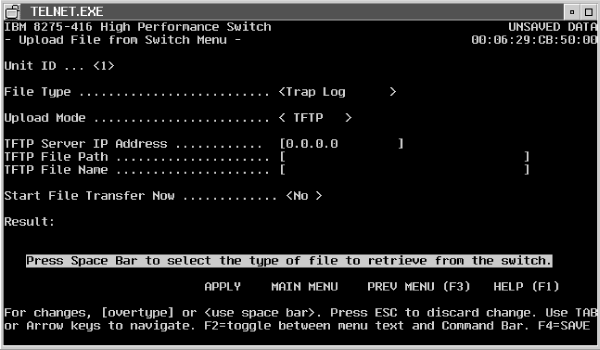
Uploading is the transfer of files from the switch to a remote server (Figure 57).
Figure 57. Uploading a file from the switch
 (artname: pmgrab76.EPS) |
The following parameters apply to uploading and downloading of files.
File path can be appended to the file name if the string is less than 17 characters. Otherwise, the File Path field will need to be used and the File Name will be appended to the File Path as is. An example would be File Path set to c:\tftp\code\ and File Name set to e1r1v1.opr.
| Note: | File Name, File Path, and TFTP Server IP Address are applicable only if the Transfer Mode is TFTP. |
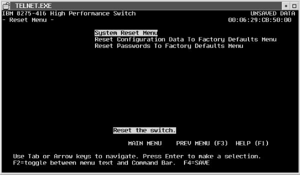
You can reset the switch without powering it off. Reset means that all network connections are terminated and the boot code executes. The switch uses the stored configuration to initialize the switch. You are prompted for confirmation if you want the reset to proceed. A successful reset is indicated by the LEDs on the switch.
After selecting Reset Menu from the System Utilities Menu, you are given the choice of the resets you can request as shown Figure 58.
 (artname: pmgrab82.EPS) |
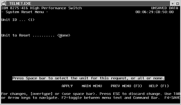
Reset the system by indicating the particular unit as shown in Figure 59. You must identify the switch to reset. None is the default.
 (artname: pmgrab77.EPS) |
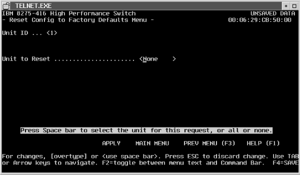
You can reset the configuration to factory default values without powering off the switch. The factory defaults are not restored until the switch is reset. The switch is automatically reset when this command is processed. You are prompted to confirm that you want the reset to proceed.
Reset the configuration data to the factory defaults by indicating the particular unit as shown in Figure 60. You must identify the switch to reset. None is the default.
Figure 60. Reset configuration data to factory defaults
 (artname: pmgrab78.EPS) |
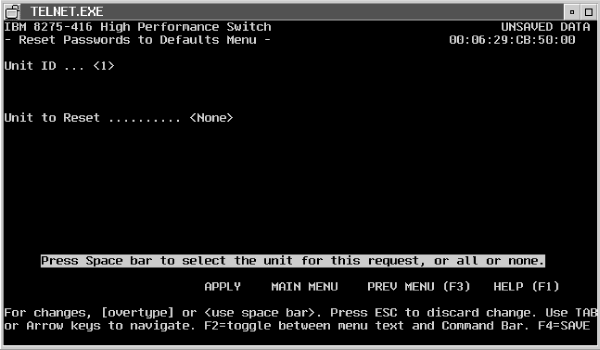
You can reset user passwords to factory default values without powering off the switch. The factory defaults are not restored until the switch is reset. The switch is automatically reset when this command is processed. You are prompted to confirm that you want the reset to proceed.
Reset the passwords by indicating the particular unit as shown in Figure 61. You must identify the switch to reset. None is the default.
Figure 61. Reset passwords to factory defaults
 (artname: pmgrab81.EPS) |